Last update:
16-Oct-2007
©1996-2007
Mike Todd
Late in the evening of Friday, 5th October, I had a bit of an accident with my 4-month-old EOS 400D when it fell from a height whilst I was taking some photographs of the night sky. Fortunately, it was insured, and by 8.30am on Tuesday 9th I had a brand new replacement from them.
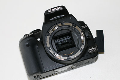
With the original basically ready to be thrown away, I thought that it might be educational to dismantle it. So I slowly took it to bits, photographing as I went. The Canon EOS 400D (as it is known in the UK, but also known as the Digital Rebel XTi) is a very neat 10Megapixel camera, complete with a "dust management" system that shakes dust away from the image sensor.
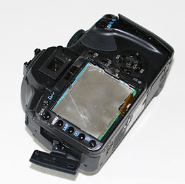
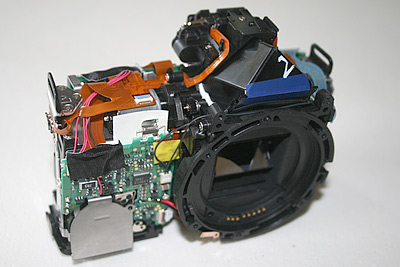
These two first pictures show the EOS as it ended up after the fall. The LCD display had come away, along with the filters for the backlight. The mirror was broken (that's what the shard of glass are), the case was badly scratched and the eyepiece was broken. Several bits of plastic inside were also rattling around but, surprisingly, the lens was completely unaffected!
Here you can see the front and back (the display still has the back-light in place, and you can't really see the cracked eyepiece).
|
|
 |
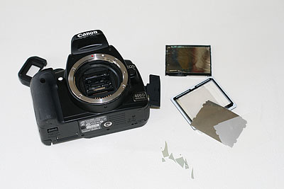
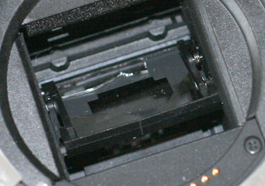
The front of the camera actually doesn't look too bad ... not surprising, since it fell on its back. But in the picture below you can just about see the damage to the mirror, although it's a little clearer on the right.
|
|
 |
And this is the point at which I dismantled the camera.
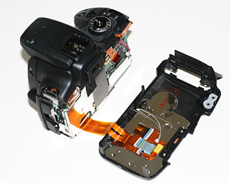
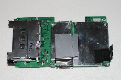
The two pictures below show the back separated from the body, revealing the main circuit board. The square chip on the right of the circuit board reads "Canon CH4-6333 ROM1 108 0714 K80 E1" and this would appear to be the main memory in which the camera's software is stored. The "0714" suggests that this chip was manufactured in week 14 of 2007. If you can see any little bits of "grit" these are from the sandstone paving that the camera hit that made their way deep inside the camera.
|
|
 |
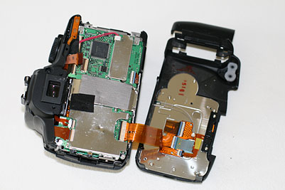
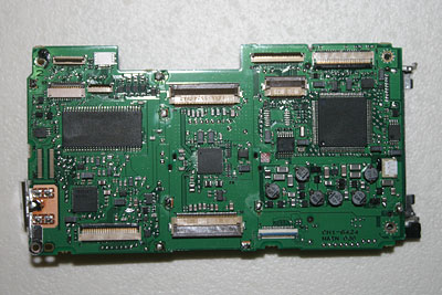
The two pictures below show additional views of the main circuit board. The first is simply the view from the back, and the other is the "front" side. The screened enclosure on the left of the second picture is the memory card slot.
 |
 |
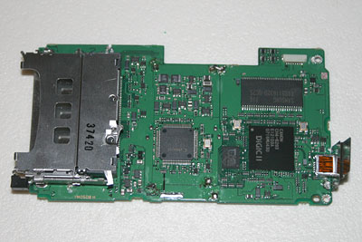
And these two pictures show the same views of the main board, but with the screening removed. There is more detail in the individual captions.
 This is the view from the back, with the ROM1 chip on the right hand side. The large chip on the left is a Samsung 512Mbit SDRAM chip. The smaller chip on the bottom left is a Sony M4006ER (possibly related to the USB port, which is on the very left). The chip right in the middle is a Canon CH4-6338 LC5010 00042 which appears to be associated with the main imaging chip which, although on the other side of the board facing forwards, connects to the two sockets top and bottom centre. |
|
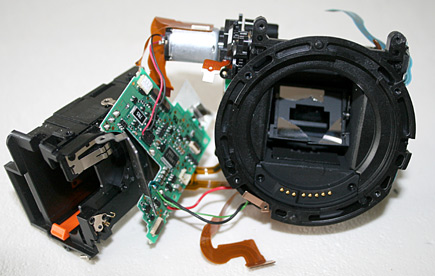
Continuing the "tour", the picture below shows the main body with the "top" removed. On the very left of the body, with the blue ribbon cable, is the flash circuitry. The top of the "prism" can also be seen, marked "2" ... of course, on this cheaper model, this isn't a true prism, but simply a mirror glued in place.
 |
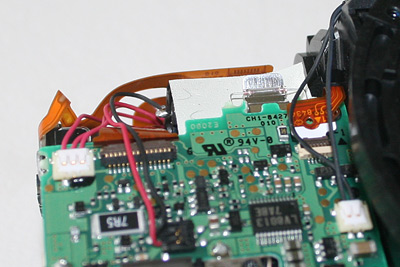
Here is the exposed body from the front, showing the blue tape providing additional security for the viewfinder mirror, and on the bottom left is the "backup" battery enclosure. The picture on the right is a close-up of the top of the circuit board, showing the bright "filament" bulb and its reflector at the top right.
 |
 |
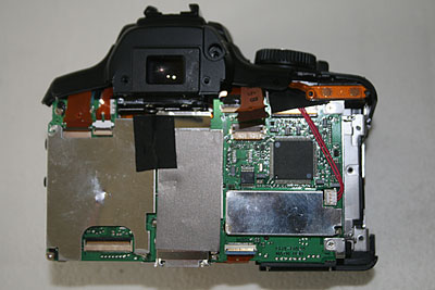
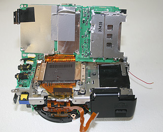
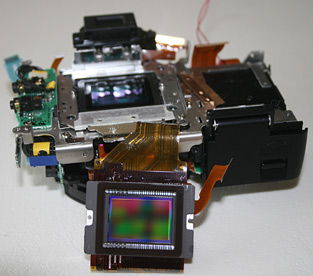
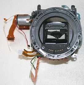
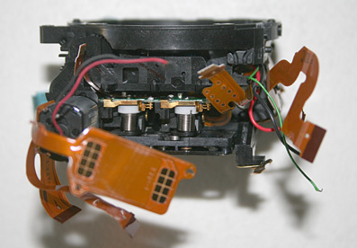
And a look round the back, just before the main circuit board was removed. It is being hinged upwards (with the battery compartment at the bottom right). It reveals the imaging chip and shows how the ribbon cable "wraps around" the main board to plug into the sockets top and bottom on the other side (as shown earlier). The chip is securely located onto a metal plate by two pins, and held in place by two phsophor-bronzeclamps.
 |
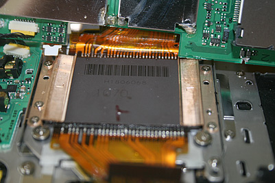 |
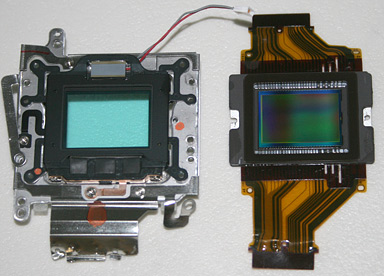
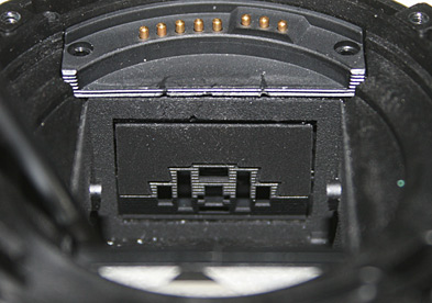
When the imaging chip is removed, the "metal plate" underneath turns out to be the mounting for the new low-pass filter with its piezo-electric "shaker". The picture on the right (with both units viewed from the light side) shows the filter, mounted with three rubber couplings at the bottom, and a number of plastic "springs" holding its frame in place. The grey oblong at the top is the piezo crystal itself, which shakes the filter, and the dust should then drop down out of the way.
 |
 |
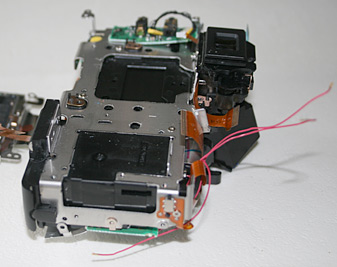
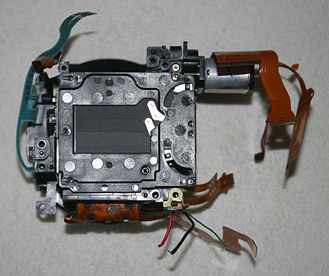
With the main board and the imaging assembly removed, the core metal core chassis of the camera is revealed. Pulling this away leaves only the shutter/mirror assembly, the front circuit board and battery compartment.
 |
 |
The next job was to "rip" apart these separate assemblies (by this time, subtle dismantling of the 400D had gone out the window). The picture on the left shows the shutter/mirror assembly, with its drive motor and gears, separated from the front circuit board and battery compartment.
 |
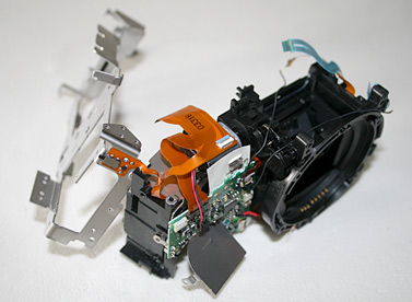
Below-left is a slightly better view of the shutter/mirror assembly. Behind the broken glass of the mirror you can just see an aperture in its mount (seen better in the previous picture). This is actually part of the metering system. The main mirror is only partially silvered, so some of the light goes straight through and bounces off a second mirror (not really visible in these photos) mounted so the the light gets reflected downwards. The focus sensors are positioned on the bottom of the chamber, and are visible in the right-hand photo below (with the mirrors held up).
 |
 |
And finally, the two pictures below show the focal-plane shutter, and the two strong springs that provide the force to drive the shutter and the mirror flip-up mechanism.
 |
 |
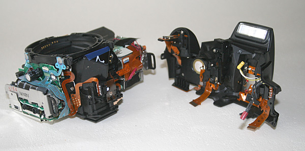
Finally, two general pictures. The first is the optical path broken apart:
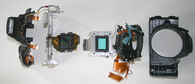 |
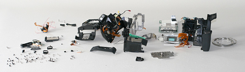
And the last picture is the table-top with all the bits laid out!
|
|